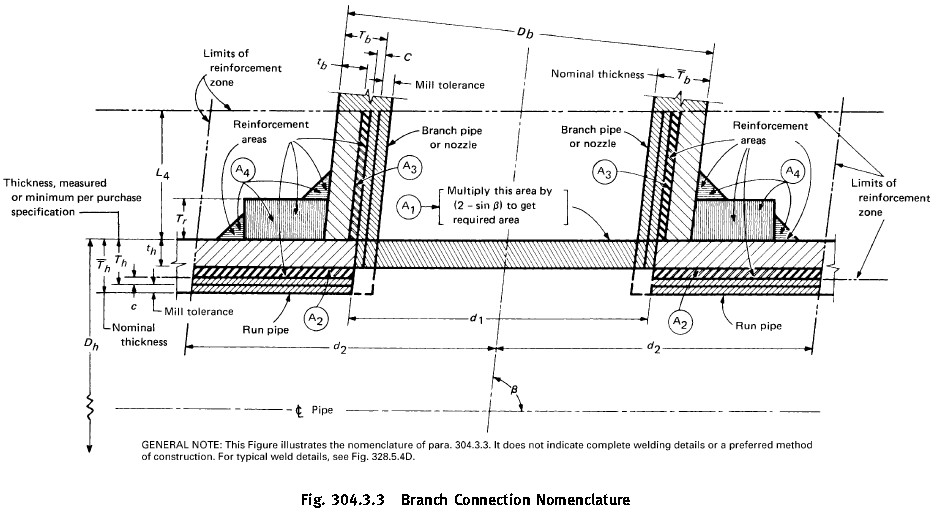
 This calculator works on the basis of criteria specified in section 304.3.3 : Reinforcement of Welded Branch Connections in ASME B31.3. This calculator calculates branch reinforcement for Internal Pressure. I have provided details of behind the back calculations at the bottom of this calculator. Your comments and suggestions are highly welcomed.
This calculator works on the basis of criteria specified in section 304.3.3 : Reinforcement of Welded Branch Connections in ASME B31.3. This calculator calculates branch reinforcement for Internal Pressure.
Input Required
- Material of Construction of Header Pipe and Branch Pipe.
- Nominal Pipe Size of Header and Branch.
- Standard Pipe Thickness e.g. STD, S40 etc. of Header and Branch.
- Corrosion allowance for header and branch pipe.
- Negative mill tolerance for Header and Branch Pipe.
- Type of Pipe Construction : Seamless, ERW or FBW for both Header and Branch.
- Design Pressure.
- Design Temperature.
- Branch Angle. Maximum angle is 90 Degree. Provide smaller angle.
Working
Specify minimum R-pad thickness. Start with 0 to check if reinforcement is required. If available reinforcement area A2+A3+A4 is less than required reinforcement area, increase size of minimum R-pad thickness gradually. Near exact size can be guessed by trial and error method when available area becomes slightly more than required area.
Then specify actual available plate/pipe thickness just more than minimum required R-pad thickness, to get width of Reinforcement Pad for the branch.
Theory
Components of Nominal Pipe Thickness
Nominal Pipe Thickness specified in Dimensional Standards such as ASME B36.10M and ASME B36.19M includes following components :
- Pressure design thickness of pipe as calculated for the given pipe material, design temperature and pressure. (‘th‘ for header and ‘tb‘ for branch). Yellow highlighted in above sketch.
- Corrosion allowance based on fluid and pipe material chemistry at particular temperature.
- Mechanical allowance for threading, grooving etc. As in this case, we are welding pipes to each other, no mechanical allowance is considered.
- Negative Mill Tolerance. After subtracting mill tolerance from nominal pipe thickness, we get minimum thickness per purchase specification. Green highlighted in above sketch.
- Extra thickness as pipe thickness of exact required thickness is never available. Only standard pipe sizes are available and we have to use next higher thickness pipe. (Blue highlighted in above sketch). This extra thickness of pipe for both header and branch acts as added reinforcement for branch connections.
Calculations
- t : Based on header and branch pipe inputs, pressure design thickness of header and branch pipes is calculated as per ASME B31.3 Section 304.1.1 For more details, see Pipe Thickness Calculation as per ASME B31.3 (‘th‘ for header and ‘tb‘ for branch).
- For explanation of all dimensions in Branch Reinforcement zone, see Figure 304.3.3 from ASME B31.3.
- d1 = effective length removed from pipe at branch. For branch intersections where the branch opening is a projection of the branch pipe inside diameter (e.g., pipe-to-pipe fabricated
branch), d1 = [Db – 2(Tb – c)]/sin ß - d2 = “half width” of reinforcement zone = d1 or (Tb – c) + (Th – c) + d1/2, whichever is greater, but in any case not more than Dh.
- L4 = height of reinforcement zone outside of run = 2.5(Th – c) or 2.5(Tb – c) + Tr whichever is less.
- Tb = branch pipe thickness (measured or minimum per purchase specification) which excludes mill tolerence.
- Th = Header pipe thickness ( (measured or minimum per purchase specification) which excludes mill tolerence.
- Tr = minimum thickness of reinforcing ring or saddle made from pipe. (Use nominal thickness if made from plate.). = O, if there is no reinforcing ring or saddle.
- ß = smaller angle between axes of branch and run.
- A1 : Required Reinforcement Area for branch under internal pressure : A1 = th X d1 (2-Sin ß).
- Actual available area is calculated as sum of three parts A2, A3 and A4. It must be more than required reinforcement area A1. i.e. A2+A3+A4 >= A1.
- Area A2 is the area resulting from excess thickness in the run pipe wall : A2 = (2d2 – d 1 ) (Th – th – C ).
- Area A3 is the area resulting from excess thickness in the branch pipe wall: A3 = 2L4(Tb-tb-c)/sin ß.
- Area A4 : Area A4 is the area of other metal provided by welds and properly attached reinforcement.
Calculation of Area A4
Area A4 consists of extra reinforcement provided by reinforcement pad, and its associated welds.
- Weld between branch and header/reinforcement pad.
- Weld between reinforcing pad and header pipe.
- Reinforcing pad cross section area.
