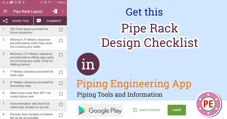
During design of Pipe Rack, certain points need to be taken into consideration for optimal design. Some of these points are covered in following pipe rack design checklist. This checklist can be used at design stage as well as during 3D Model Review.
| Sr | Check Item | Done |
| 1 | 25% Extra space provided for future expansion | |
| 2 | Minimum 3* Meters clearance provided below Units Pipe racks not crossing any roads. | |
| 3 | Minimum 2.2* Meters clearance provided below offsite pipe racks not crossing any roads. (Only for Walking below). | |
| 4 | 7* Meters clearance provided for main road | |
| 5 | 6* Meters clearance provided for Secondary road. | |
| 6 | Water lines more than 30?* not routed above rack | |
| 7 | Instrumentation and electrical cable trays located on top tier | |
| 8 | Process lines located on bottom tier as far as possible. | |
| 9 | Utility lines and hot process lines located on upper tier. | |
| 10 | Bigger size lines kept near rack columns. | |
| 11 | Minimum spacing between pipes based on Bigger size flange. | |
| 12 | Thermla expansion at bends, branches taken into consideration for pipe spacing | |
| 13 | Anchors in pipes at the anchor bay if such bay is provided | |
| 14 | If no anchor bay provided, Anchors are distributed throught rack | |
| 15 | Orificemeter runs are near the columns for access by portable ladder. | |
| 16 | Lines requiring thermal loops are near the edge of rack. | |
| 17 | Small bore line size increased to 2? on rack. | |
| 18 | Fire proofing provided for pipe rack |
Note :
* These clearances shall be as per Piping Design Basis for the particular project.
[google-square-ad]

