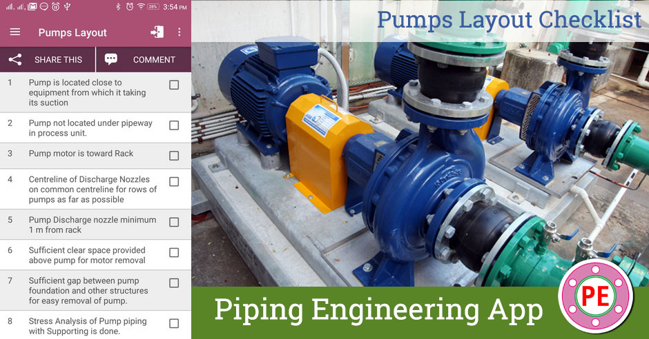
During design of Pumps Equipment Layout and Piping Layout, certain points need to be taken into consideration for optimal design. Some of these points are covered in following checklist. This checklist can be used at design stage as well as during 3D Model Review.
| Sr | Check Item | Done |
| 1 | Pump is located close to equipment from which it taking its suction | |
| 2 | Pump not located under pipeway in process unit. | |
| 3 | Pump motor is toward Rack | |
| 4 | Centreline of Discharge Nozzles on common centreline for rows of pumps as far as possible | |
| 5 | Pump Discharge nozzle minimum 1 m from rack | |
| 6 | Sufficient clear space provided above pump for motor removal | |
| 7 | Sufficient gap between pump foundation and other structures for easy removal of pump. | |
| 8 | Stress Analysis of Pump piping with Supporting is done. | |
| 9 | Pump nozzle loading due to piping is less than vendor allowables | |
| 10 | Strainer in Suction is easily removable. | |
| 11 | Check valve installed in discharge line of centrifugal pump. | |
| 12 | Strainer is located before any reduction in pipe size. | |
| 13 | Suction piping minimised to reduce pressure drop and vapour pockets. | |
| 14 | Pump NPSH Checking done with process department | |
| 15 | Top flat reducer as close as possible to Suction nozzle for front suction nozzle pump. | |
| 16 | Piping Valves readily operable from grade | |
| 17 | Handwheels of Valves within perimeter of pumps as far as possible. | |
| 18 | Clear Aisle of 1000 mm available between adjacent pumps | |
| 19 | Monorail provided for large pumps if no access possible for mobile equipment. (>= 75KW) | |
| 20 | Pump not located within funded (dyked) tank areas. | |
| 21 | Pumps not located below equipment handling hydrocarbon liquids. | |
| 22 | Water Sprinkler / Spray system provided for pumps handling class A Fluids. |
[google-square-ad]

