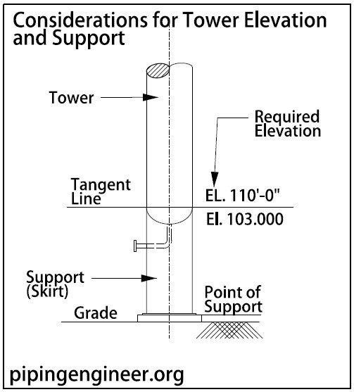
Tower elevation is the distance from grade to the bottom tangent line of the vessel. Support is the means by which the vessel is retained the the required elevation.
The first step in tower layout is setting the bottom tangent line elevation. This step assists civil engineering in foundation design, vessel engineering in support design, systems engineering in line sizing, and rotating equipment engineering in pump selection.
To set the elevation of tower, the plant layout designer requires the following information:
a. Tower dimensions
b. Type of heads
c. Support details
d. NPSH requirements
e. Bottom outlet size
f. Reboiler Details
g. Foundation Details
h. Minimum Clearances.
Drawing below shows an example of elevation and support.
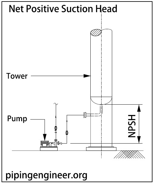
Although tower elevation must satisfy minimum NPSH requirements, it can be set by a combination of the following constraints – whichever produces the minimum tangent line elevation:
Net Positive Suction Head
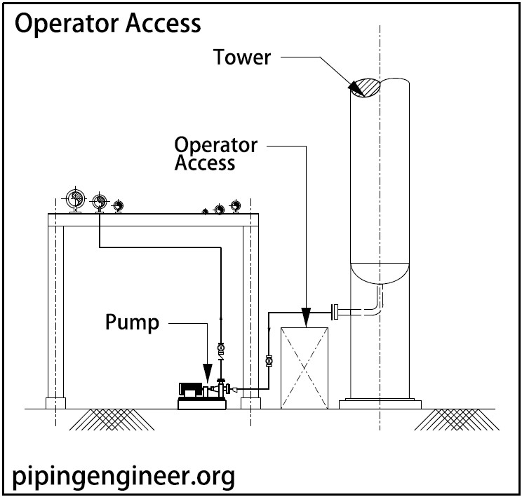
Operator Access
Operator access near distillation tower and bottoms pump must be taken into consideration while deciding elevation of tower. Typical elevation requirement is 2100 mm.
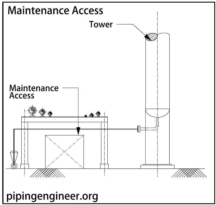
Maintenance Access
Maintenance access required below the rack adjacent to distillation tower must be taken into consideration when bottoms line is passing across and below the rack.
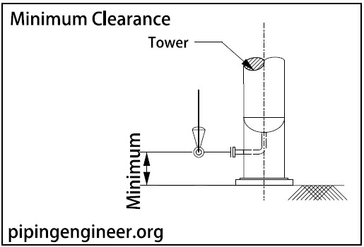
Minimum Clearance
When control station in bottoms line is immediately located near the distillation tower, minimum clearance required for lines running on floor must be maintained as per project specification.
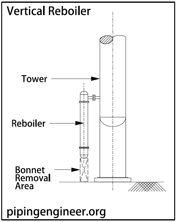
Vertical Reboiler
When a vertical reboiler is connected to distillation tower immediately on nozzles, height of reboiler and bonnet removal area required below the reboiler is a prime deciding factor for bottom tangent line elevation of a distillation tower.
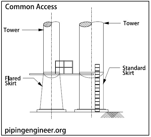
Common Access
Sometimes, two distillation towers are located near to each other. In such a case, common platforms with common access are provided for these towers. In such a case, elevation of towers can be decided based on common platform elevation.
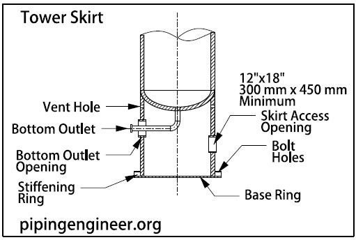
A Skirt is the most frequently used and most satisfactory means of support for vertical vessels. It is attached by continuous welding to the bottom head of the vessel and is furnished with a base ring, which is secured to a concrete foundation or structural frame by means of anchor bolts.
In most cases, the skirt is straight, but on tall, small diameter towers, the skirt could be flared. Access openings are required in vessel skirts for inspection and when possible, should be orientated toward the main access way.
Following figure shows a typical skirt arrangement.
Sample Tower Elevation Calculation
For example, the tangent line elevation of the tower as shown below has been set using the following information and the guidelines in this handbook.
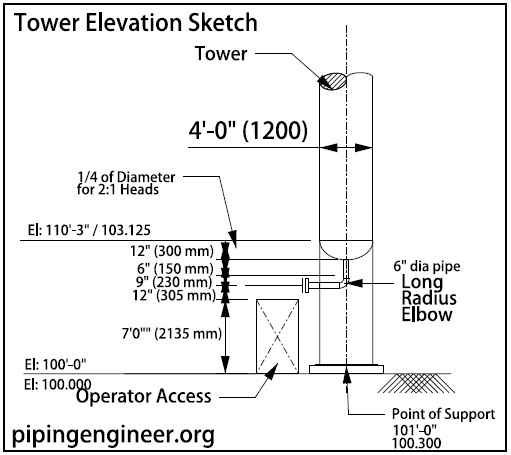
Configuration
- Tower dimensions – 4 ft 1200 mm in diameter by 60 ft (18 300mm) in length
- Type of heads – 2:1 elliptical
- Support : Straight skirt with base ring
- NPSH – 6 ft (1800 mm Minimum)
- Bottom outlet size – 6 in diameter
- Foundation – Concrete point of support elevation of 101 ft (100,300 mm)
- Operator clearance – 7 ft (2100 mm)
A freehand sketch should be used for this exercise. Although the minimum NPSH requirement was a key factor in elevating the tower in this example, the height was finally dictated by operator access clearance, which was the greater of the two dimensions.
If the configuration shown below had been used, the tangent line elevation would be 108.5 ft (102,600 mm).
