| Process Instrumentation | Flow Measurement |
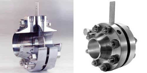
This is the most common type of flow meter used in process industry. It consists of an orifice plate with a pair of orifice flanges, which are tapped to receive sensing connections. Complete assembly consists of an orifice plate, orifice flanges, bolts and gaskets along with valved tapping connections to differential pressure transmitter.
Tapping connections are normally 1/2″. The transmitter is located adjacent to the assembly before it is connected to the remote panel and controlling device (e.g. a control valve or vessel level controller).
Orifice Flow Meter works on the principal of reduced pressure just downstream of orifice plate due to reduced flow diameter for the fluid. Increase in velocity due to reduced cross section results in reduced pressure. Differential pressure is proportional to the flow velocity and density of the fluid.
Installation in Piping Network
- Orifice flanges need not be accessible from grade or a platform but should be positioned at a location and elevation that can be reached by a portable ladder.
- Care should be taken at horizontal banks of lines to allow for adequate space for side mounted taps and when required, close-coupled transmitters.
- Depending on service, orifice flanges can be mounted in the vertical and the horizontal sections of piping as per instrument hookup drawing.
- Orifice flanges shall be located adjacent to walkways, platforms, or structures.
- Orifice Flanges shall be installed in horizontal pipe runs, wherever possible.
- Orifice flanges shall have threaded taps.
- Orifice flanges with a centerline elevation 4500 mm above the high point of finish surface, except pipeways, shall be accessible from a platform or permanent ladder.
- Straightening Vanes shall not be used.
[google-square-ad]
Straight Run Requirements
- Orifice meter runs require straight runs upstream and dowstream so that flow passing through it is laminar flow instead of turbulent flow.
- Most of the time, downstream straight length required is 5 times Diameter of the pipe.
- Upstream straight length requirement varies based on type of components immediately upstream of the orifice meter.
- Straight run between orifice meter and a upstream throttling valve is usually 39D.
- Straight run between orifice meter and a upstream fully open gate valve is usually 14D.
- Straight run between orifice meter and a upstream Tee or Cross is usually 31D.
- Straight run between orifice meter and a upstream reducer is usually 14D.Straight run between orifice meter and a upstream throttling valve is usually 39D.
- Straight run between orifice meter and a upstream elbow depends on the relative angle of next elbow upstream of the immediate elbow. Usually 14D to 31D.
Orifice Flange Tap Orientations.
- For clean liquid, Orifice flanges can be in horizontal or vertical (Upward Flow) and tap locations Horizontal.
- For Liquids with solids, Orifice flanges should be in vertical pipe with downward flow and tap locations Horizontal.
- For steam, orifice flanges can be in horizontal or vertical (Downward Flow Only) and tap locations horizontal.
- For dry gas or air, orifice flanges can be in horizontal or vertical pipe with taps in vertical position.
- For wet gas or air, orifice flanges can be in horizontal or vertical (Downward flow only) with tap locations vertical.

Check out these youtube videos to better understand them.
The Differential Pressure Flow Measuring Principle
Orifice Plate Theory
| Process Instrumentation | Flow Measurement |
