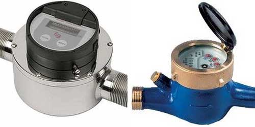
Maintaining proper flow of fluids in a process system is essential to maintain correct supply of raw materials to reactors, correct supply of water or steam for cooling or heating purpose etc. Flow meters sense the amount of flow passing through a particular pipe and sends this information to process controller which then applies process logic and sends control information to control valves or pump control unit.
A variety of flow meters are used in process industry depending on type of fluid, operating temperatures and pressures, required flow accuracy and economy. Most of the flow meters require proper flow pattern established in pipe. Flow turbulence can affect accuracy of readings. Hence they have straight pipe requirements without any branches upstream and downstream of them. These are provided by instrument department and instrument vendor. They must be strictly adhered to.
Here is a brief description of all these flow meters sufficient from piping engineering point of view.
 |  | |
| Process Instrumentation Flow Measurement This is the most common type of flow meter used in process industry. …Read More.. | ||
Rotameter
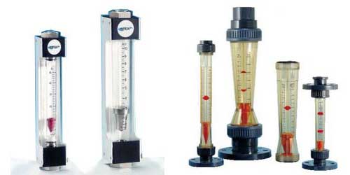
Rotameter is also known as Variable Area Flow Meter due to variable cross section of this meter. This flow meter consists of a tapered tube, usually made of glass, with a float inside that is pushed up by the fluid flow and pulled down by the gravity.
With increasing flow, the fluid viscosity and pressure forces on the float increases, making it rise until it becomes stationary at an elevation where these forces balance out against gravity.
Shapes of floats are mostly spheres and spherical ellipse type. Some of these floats are designed to spin so that operator can guess if float is stuck at the location or working properly.
Rotameters are used for wide range of liquids but are most commonly used for water or air. They can be made to reliably measure flow down to 1% accuracy.
 |  | |
| Process Instrumentation Flow Measurement Coriolis Mass Flow Meter is widely used flow meter in process industry for …Read More.. | ||
Electromagnetic Flow Meter
Electromagnetic flow meter, also called magnetic flow meter, is one of the most common flow meter in process industry.
This flow meter works on the principal of electromagnetic induction. When an electric conductor moves in a magnetic field, potential difference is induced across the conductor. This potential difference can be measured to infer the speed of conductor movement.
In this case, a conducting fluid such as water acts as a electric conductor. Water contains ions which help it conduct electricity. Magnetic field is applied to the stainless steel metering tube, lined with insulating material like plastic. This results in potential difference across fluid which is proportional to the flow velocity perpendicular to the magnetic flux lines.
Usually electrochemical and other effects at the electrodes make the potential difference drift up and down, making it hard to determine the fluid flow induced potential difference.
To mitigate this, the magnetic field is constantly reversed, cancelling out the static potential difference. This however impedes the use of permanent magnets for magnetic flow meters.
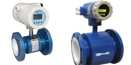
Single Jet Flow Meter
A single jet meter consists of a simple impeller. This impeller has radial vanes. A Single jet of fluid rotates the impeller. Rotations of the impeller are counted mechanically or electronically to get the cumulative flow. They are increasingly being used in UK for larger sizes are commonplace in the European Union.
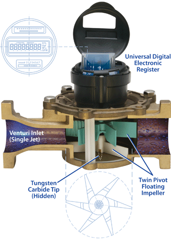
Rotary Piston Flow Meter
This flow meter has a disc with an annular groove on its underside. This groove is capable of holding the fluid and transporting it from the chamber inlet to the chamber outlet. Some fluid also gets transported in a cavity formed between rotor outside wall and the chamber inside wall.
The centre shaft under the rotor runs in a circular groove in the body. A wall in the body is engaged with a slot in the rotor. This changes rotation into an oscillation movement which compartmentalizes the fluid into positively displaced pockets.
A magnetic sensor or a mechanical gear train measure the fluid flow. Metering repeatability is better than 0.2% and meter accuracy of 1%. Accuracy can be improved using electronics circuit as difference between actual flow rate and measured flow rate is consistent at low flow rates.
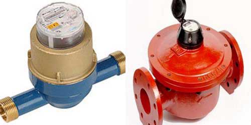
Multiple Jet Flow Meter
This is a velocity type flow meter. It includes a horizontal impeller mounted on a vertical shaft. Impeller is installed in a housing with multiple inlet ports all of which direct fluid onto the impleller, and thus rotating it.
Rotation of impeller is proportional to the velocity of the flowing fluid.
Impingement of fluid on the impeller via several ports ensures even wearing of the impeller and shaft and thus reduces early damage.
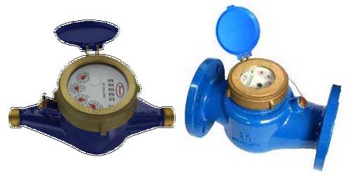
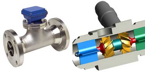
Turbine Flow Meter
This flow meter consists of a turbine, mounted axial to the pipe, and rotates due to flow of fluid. Number of rotations per unit of time are counted to get the flow rate. Initially, turbine speed is not proportional to flow rate. But as steady state is reached, speed of turbine becomes proportional to fluid velocity.
Turbine flow meters are used for the measurement of natural gas and liquid flow. Although turbine flow meters are relatively less accurate than displacement type and jet type flow meters, they occupy very less space inside the fluid path and thus do not restrict the flow severely. Pressure drop is very less.
They are mostly used by large commercial users and as master meters for the water distribution system. Strainers are generally required to be installed in front of the meter to protect the measuring element from gravel or other debris that could enter the water distribution system.
Turbine meters are generally available for 1-1/2″ to 12″ or higher pipe sizes. Body of a turbine meter is commonly made of bronze, cast Iron, or ductile iron. Internals can be plastic or non-corrosive metal alloys.
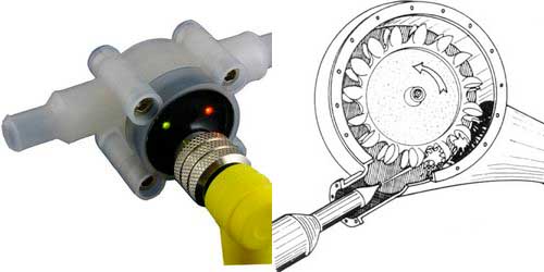
Pelton Wheel Flow Meter
It consists of a horizontally mounted pelton when on a vertical shaft. Fluid impinges upon the pelton wheel and rotates it. Rotations are counted per time period and translated into user readable flow rates such as gallons per minute, liters per minute etc.
Tendency of pelton wheel is to have all the flow travelling around it with the inlet flow focused on the blades by a jet.
Originally, pelton wheels were used for power generation.
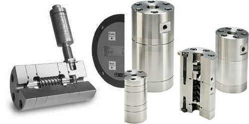
Helical Gear Flow Meter
This type of flow meter consists of helical shaped gears or rotors. These rotors are in the shape of a helix, a spiral shaped structure. When fluid enters the meters, it flows through the compartments in the rotors, causing it to rotate. Speed of rotation can be measured to calculate the flow rate.
 |  | |
| Ventury flow meter works on the principle of Ventury Effect. A reduction in fluid pressure …Read More.. | ||
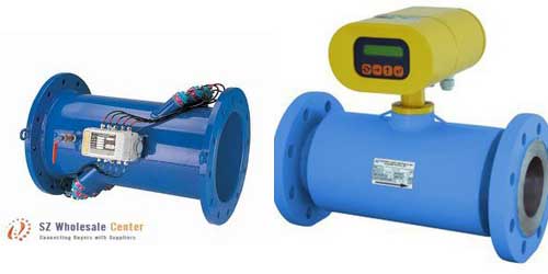
Ultrasonic Flow Meter
This flow meter uses the principal of ultrasound to measure the velocity of gas or liquid. It uses multiple ultrasonic transducers, installed at an inclined angle to the pipe. One pair of ultrasonic transmitter and receiver is installed opposite to each other with transmitter at downstream flow direction and receiver at upstream flow direction. Other pair of transmitter and receiver is installed with transmitter at upstream direction and receiver at downstream direction.
The average velocity of fluid along the path of ultrasound is measured by averaging the difference in measured transit time between the pulses of ultrasound propagating into and against the direction of the flow.
Readings are affected by the conditions of the fluid such as temperature, density and viscosity. But they are expensive to use due to lack of moving parts like mechanical flow meters.
There are three types of ultrasonic flow meters. Transmission flow meters, inline(intrusive, wetted) flow meters and clamp-on(non-intrusive) flow meters. Ultrasonic flow meters that use the Doppler shift are called Reflection or Doppler flow meters. One more type is Open-Channel flow meter.
Check out these youtube videos to better understand them.
Oval Gear Flow Meter
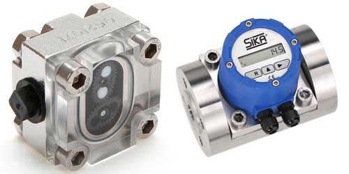
The oval gear flow meter is a kind of Positive Displacement Flow Meter. As the fluid being measured passes thru the meter, it rotates 2 oval gears in measuring cavity to displace a precise volume of fluid.
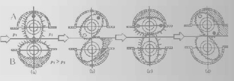
A sensor detects the gear rotation to determine displaced volume and flow rate. Fluid pressure rotates the oval gear, Figure 1. In position (a), the fluid exerts a clockwise driving force on gear A. there is no driving force on gear B. It is perpendicular to the flow so the fluid forces are balanced around the shaft. As the gear rotate to position (b), the fluid being to exert a force on gear B. At position (c), all the driving force is on the gear B. This alternating driving force provides a smooth rotation of almost constant torque.
The meter design minimizes the slippage between the gears and the measuring cavity wall. As a result, the oval meter is less affected than other designs by the liquid’s viscosity and lubricity.
Applications
Oval gear flowmeter is mainly used for high value liquids such as oil, chemical etc. Main applications include unloading, transfer and consumption monitoring.
Features
- Only Two Moving Parts
- Higher Accuracy, 0.5% or 0.2%.
- Standard Viscosity up to 5,000 cP(Centipoises = mPa.s).
- Size of wide flow ranges 0.04-340 M3/h (18-37,396GPM).
- Wide range of working environment –20 ~ +280 o C
Nutating Disc Flow Meter
Nutating disc flow meter is used for measuring water supply. It is a reliable flow measurement device within 1 percent. This flow meter is used since last 100 years and it is highly reliable.Its function is unaffected by viscosity of the fluid and any other flow profile disturbances. It can handle suspended solids where other types of flow meters can malfunction.
This flow meter works both with a mechanical register as well as electronic registers. It can operate upto 150 PSI pressure and temperatures of upto 250 degree F.
This device consists of an eccentrically mounted nutating disc or wobbling disc which rotates when the fluid passes through it. Its rotations are counted by the mechanical or electronic register and thus gives direct indication of amount of fluid passing through it.
